 The
Architecture of the
WSM Decision Support System
The
Architecture of the
WSM Decision Support System
and the GIS Database
|
1 The
architecture of the Decision Support
System
|
|
The
Decision Support System has been
implemented in Visual Basic .NET
using the Arc Objects COM
technology by ESRI, which is
also the platform for the GIS
Database. The tool was designed
according to the four step
schema presented in Fig. 1 that
involves: (a) the database; (b)
the object model linked to
mathematical models for water
allocation, quality and economic
estimations, (c) a logical
coordination unit, responsible
for the communication with
external models, and (d) the
user interface that allows for
the definition of data and
simulation parameters, and the
presentation of results through
customizable charts, tables and
maps. |
Special
attention has been given to the
portability of the DSS. The
developed object model and the
linked mathematical models can
easily be transported to other GIS
environments while most GIS
functions are generic, implemented
outside the modelling procedures and
algorithms.
The user of the
DSS is not necessarily a
hydrologist, an engineer or an
economist; such expertise however
can be
useful during the setup stage when
defining the case study region.
|
|
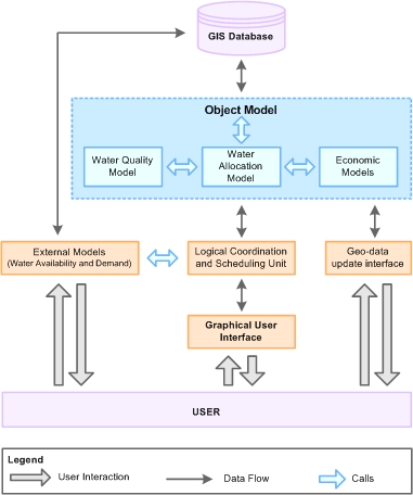
Figure 1. The WSM DSS architecture
|
|
|
2
The GIS
Database
|
|
The GIS Database is the heart of the
spatial information system and provides
the central storage system that allows
communication and intermediate storage
between the models. The
Database is strictly interrelated with
the methodology applied in analyzing and
simulating water resource systems and
consequently with the WSM Decision
Support System. The Data Model has been
developed under
Arc GIS 8.1. The main output of the data
model is an Arc Info geodatabase, which
stores information on all spatial and
non-spatial attributes and classes
included within the model.
Besides the accommodation of available
data and the selection of the
appropriate platform for facilitating
data collection and entering, the GIS
Data Model has been developed keeping in
mind the final goal of the WSM DSS,
which is the analysis of water
management strategies in the project
case study area. To this end, the Data
model is able to:
-
to accommodate
all data related to the simulation
of different water availability
scenarios and demand forecasts,
including forecasts of pressures;
-
to store
information on the different water
management instruments proposed for
the different case studies of the
project.
Since the spatial
scale of the case studies is variable
ranging from a river basin in Portugal (Ribeiras
do Algarve) to a small Greek island in the Aegean Sea, one primary aim
achieved during the development and the
implementation of the data model was to
allow for the modelling of those very
different systems under a unique but
flexible framework.
|
In this context,
the design of the Database was performed
in such a way as to adequately
describe any system in terms of water
resources availability, demand,
infrastructure and management options
and developmental policies to be
formulated within the scope of the
analysis.
Within the model,
logically related features are grouped
together. Thus, the model extends the
basic distinctions between water
resource systems, demands,
infrastructure and administrative
structures. The core components of the
Data Model are:
-
Basic
Regional Data, organizing general
information of the case study area.
-
Water
Bodies, representing the
most important water bodies, as those
are classified in the Water Framework
Directive, and the monitoring network.
-
Water
Network Data, for modelling the
water resource system and
infrastructures of the case study
region.
-
Administrative
Structures, standing for
the administrative organization of the
region.
-
Time
Series, modelling time series data,
mostly related to water network objects.
It should be noted
that in the approach adopted during the
development of the WSM Data Model, some
features are represented both as simple
features (i.e. points, lines and
polygons) and as a complex water
network. This allows for the
accurate representation of the physical
entity (e.g. a lake) and for the
particular modelling requirements set
out by the Decision Support System.
|
|
|
3 The Object
Model of the WSM Decision Support
System
|
|
The
Object Model of the WSM DSS is
formulated around the concept of an
ESRI geometric network. A geometric
network is described as a set of
junctions (points) and edges (polylines)
that are topologically connected to
each other. The network is used to
describe the connectivity of flow
through the modelled system,
incorporating different supply
sources, demands and requirements as
well as treatment points or
monitoring stations.
In the Object Model junction
elements are conceptualized as
water nodes while the edges that
stand for the connections between
them are the water links.
The objects and their functionality
are strictly related to the
Water Allocation
procedure and algorithms.
Water nodes are classified into
three categories (Figure 2):
-
Supply nodes, standing for
alternative water supply sources
and characterized by the monthly
available supply;
-
Demand nodes, modelling
water uses and flow requirements
and,
-
Transhipment
nodes, representing treatment plants and
generic network junctions.
Supply nodes conceptually
provide water to demanding users
through the outgoing links, thus
having a water source function, but
some of them also have ingoing
links, functioning as water
accumulators or final receptor bodies.
Those are:
-
Renewable Groundwater,
representing shallow, free
groundwater that is continuously
recharged by the hydrological
cycle. A renewable groundwater
is a water source with the
further roles of accumulator and
receptor body of return flows
(end node).
-
Coastal
Zone, conceptualising
a coastal area where seawater is
abstracted for desalination, or
quality status such as eutrophication is monitored. A
coastal zone is a water source
and also an end node. As a
receptor body, it can receive
the return flows from
consumptive uses and recharges
from aquifers.
-
River
Reach. For the
modelling purposes of the DSS a
river and its tributaries are
divided into “river reaches” by
a certain number of cross
sections. Each river reach is
characterised by a physical
branch of the river and by its
downstream section. A river
reach is schematically
represented by one river node.
-
Reservoir (Storage + Small +
Natural Lake),
conceptualising three types of
reservoirs: a man-made storage
reservoir fed either by a
natural water course or by
pipelines, a small artificial
reservoir built to collect
rainfall or run-off from a
catchment area, or a natural
surface lake. A reservoir is a
water source with the further
roles of accumulator and
receptor body.
-
Importing, standing for
water transfers from
a neighbouring area. As a supply
node it has the role of water
source.
-
Fossil
Groundwater, conceptualising deep, confined
groundwater that is not
recharged by the hydrological
cycle. Fossil groundwater is a
water source but not an
accumulator or an end node
because it has a no recharge.
|
Demand nodes are:
-
Settlement,
conceptualising
the civil urban
population and infrastructures
of a defined area, i.e. a
city, a town or a village.
-
Tourist site,
representing
a tourist community
exerting a seasonal water
demand.
-
Irrigation
site, standing for the activity of
cultivating land either for the
survival of land-owners or for
commercial purposes.
-
Industrial
site, representing a
productive site producing or
supplying goods, services etc.
An Industrial Site can be public
or private, and is also characterised by its field of
application: Petrochemical,
Electronics, Aerospace, Food and
Beverage, Pulp and Paper,
Textile etc
-
Animal
Breeding, describing the
activities of livestock breeding.
-
Exporting,
representing the amount of
water to be exported to a neighbouring area.
-
Hydro-electricity production,
which takes into account the
amount of water requested by a
single plant or a group of
plants to generate electricity
from falling or fast-flowing
water.
- Environmental,
recreation and navigation
requirements, representing non-consumptive demand nodes aiming
to address the minimum water
requirements of rivers, or the water
needs for recreational purposes and
navigation.
Three types of Treatment Plants are
considered in the DSS:
-
Drinking Water
Treatment Plant,
standing for a
plant treating water in order to
make it safe and acceptable
for human consumption.
-
Wastewater
Treatment Plant,
describing a
plant treating water in order to
remove or at least abate pollutant
concentrations before water is
re-used or discharged into a
body of surface water.
-
Desalination,
conceptualising a plant removing
dissolved salts from seawater,
brackish water or highly mineralized
groundwater.
Two
Transhipment
nodes have been formalised:
-
Network Reservoir, which
represents a physical reservoir
of very small capacity, which is used to
serve the needs of settlements,
tourist sites etc. Its contribution
in the water allocation is not
significant at the monthly time
scale used within the WSM
simulations. However, as a part of
the infrastructure, it has costs for
construction, operation etc that can
be accounted for.
-
Generic
network junction, used for
maintaining network connectivity
and used as an intersection
point between links.
|
|
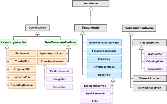
Figure 2. Overview of the object
model for water nodes |
|
The
Water Links of the conceptual
water network have two generic
characteristic variables:
-
the link
capacity, which represents the
maximum monthly flows allowed, and
-
the monthly
flow rate, that is the decision
variable of the
Water Allocation algorithm.
Water
link objects are classified in four
categories based on the
connectivity rules of the network
and the particular modeling
requirements of the DSS:
-
Supply links (pipelines and
canals) conveying water from supply
sources to demand nodes,
-
Groundwater interaction links
(recharge and discharge links),
representing the natural interaction
between surface and groundwater
bodies,
-
Return flow links, conveying
return flows from consumptive demand
uses to receptor bodies (surface or
groundwater) or wastewater treatment
plants, and
-
River links representing the
natural course of a river water
body.
|
The WSM Data and Object Models
implicitly specify a number of
connectivity rules, in order to
ensure the proper modelling of a
water resource system and its
correct simulation by the WSM
Decision Support System. Modelling
requires that some types of edges
(water links) have a specific type
of start or end junction, or both.
For example, groundwater recharge
links can only originate from
surface water nodes (reservoirs and
river reaches) and should end only
at renewable groundwater nodes.
Additionally, junctions modelling
particular types of water sources
such as non-renewable (fossil
groundwater) or importing from
neighbouring regions cannot have
incoming edges of any type. To
ensure therefore the integrity of
network data within the database,
network connectivity is modelled
within the WSM Decision Support
System, with a set of rules that
specify which type of junction can
be connected to on other junction
type, and with what type of edge. |
|
|
|
